Table of contents
If one doesn’t over-engineer, does one even live?
A question that boggles my mind from time to time. I find myself daydreaming about automating every inch of my existence. Our lives would be boring without the problems which we cast upon ourselves.
The issue of unawareness
Around 3 years ago I was chilling in the living room when I saw my wife executing the same routine I saw her do many times before. She was grabbing an empty bottle, filling it up with water, walking to the balcony and pouring that same water over the non-sentient greenery.
No more, I thought.
This straightforward, utterly simple process, needs to be done by a machine. Why would she waste those 55 calories and 120 seconds to perform such a meaningless task? Besides that, she repeated it daily.
The master plan
I wiped the whiteboard and wrote down the opportunities and approaches surrounding the problem. The key points of the solution were as follows:
- No more daily routine. Make the greenies tell us when they need water.
- When thirst is expressed, it shall be quenched.
- We may only interact with the system once a month
Obtaining the prerequisites
Since I was building a proof of concept, there wasn’t a need for sturdy materials or expensive parts. I decided to use the parts which I already had lying around just to build this Frankenstein of an irrigation system.
Around that time I decided to abandon Adobe Photoshop as my main graphic tool and transfer to Figma, due to its high availability and free storage through the cloud. I had minor adaptability hiccups due to the lack of previously known shortcuts, but since I needed a simple sketch, the time difference was irrelevant.
Thus, a sketch was born.

One might say that the sketch is a proof of concept, as well. And one would be right.
The 12V power brick needs to power the water pump, but it also needs to give a couple of volts to the microcontroller. This is why the system is bypassed by a voltage regulator which splits and scales the voltage accordingly. This is an off-the-shelf solution bundled in a module with switches for 3/5V.
The job of the microcontroller is only to control the relay switch.

If you are unfamiliar with a relay switch, think of your regular wall switch which you use to toggle the lights, which cannot be turned on by hand, but by applying a current. The microcontroller can give an output through one of its pins, which turns the switch on.
When the switch is on, the motor pumps water through the hose and provides water to whatever is waiting on the end of it.
The system will be monitored by a capacitive moisture sensor, which you can read more about in a former blog post.
The fiasco
At first, the thought of running wires which power an electric motor through a bunch of water by self-soldering and isolating seemed like an accident waiting to happen. The doubt of being executed by a static plant-watering robot was not something that I wanted to be written in my obituary. But the Internet had cleared my doubts.
The system won’t do any damage and if a fire arises, the water surrounding it will put it out. For the sake of wanting-to-do-this let’s just go with this funky logic.
And who would have thought… it worked like a charm. It had no leaks of electricity to the water or the other way around.
It failed in a much simple manner.
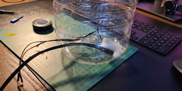
Who would have known, but if you cut a hole in a plastic bottle, no material on this planet will help you to patch the hole. I glue-gunned it. I super glued it. I melted plastic. I duct-taped it. Nothing helped!

Why the hole? Well, it was clear as a whistle that I should have as little wiring for the water pump going through the water as possible. So I drilled a hole at the bottom of the bottle and pushed the wires through it.

A successful attempt
We learn by failing. It seems had to do it the non-greedy way. I threw the bottle away and grabbed another one, in which I guided all the wires and tubes through the bottle cap.
And guess what…It worked without leaking!
A digital interface
All that was left was to integrate it with my self-hosted Home Assistant server. I chose to check the sensor in regular intervals, and if the reported moisture from the sensor fell below a certain threshold, pump the water for 10 seconds. This way I’d prolonged the life of the moisture sensor.
This is done by creating a new automation in the HomeAssistant settings. We only need to provide three things.
- a time pattern trigger to execute the automation every hour
- a numeric state condition to execute the automation only if the value of the moisture sensor falls below 60%
- two actions to execute
- turn on the water pump
- turn off the water pump after 10 seconds
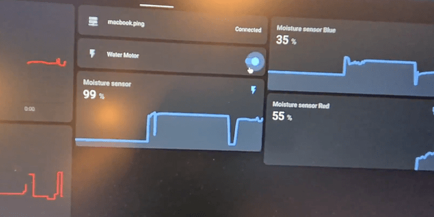
During the testing phase which lasted a couple of weeks, I exposed the moisture graphs and the switch for the pump to the HA Lovelace interface to manually observe and override.

To conclude
A prototype is built and the concept is proven. We failed fast but recovered quickly.
The PoC didn’t end here but evolved into something much greater — stable and efficient.
But, more on that soon. Until then, I hope this motivates someone to learn something new, to fail, to adapt. 🛠️
Leave a ❤️ or two to support my further shenanigans.


